| The Intake or Admission Stroke | |
|---|---|
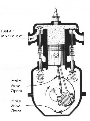 | |
| During the intake or admission stroke, the piston moves downward as a charge of combustible fuel and air is admitted into the cylinder through the open intake valve. At the completion of this stroke the intake valve closes. This is event No. 1. |
| The Compression Stroke | |
|---|---|
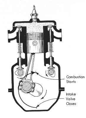 | |
| During the compression stroke, the crankshaft continues to rotate, the piston is forced upward in the cylinder, and both intake and exhaust valves are closed. The movement of the piston upward compresses the fuel-air mixture. This is event No. 2. | |
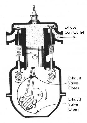
As the piston approaches the top of its stroke within the cylinder, an electric spark jumps across the points of the spark plugs and ignites the compressed fuel-air mixture. This is the ignition event, or event No. 3. The intake and exhaust valves are closed. Having been ignited, the fuel-air mixture burns. It expands as it burns and drives the piston downward. This causes the crankshaft to revolve. Since it is the only stroke and event that furnishes power to the crankshaft, it is usually called the power stroke, although it is sometimes called the expansion stroke for purposes of instruction. This is event No. 4. The intake and exhaust valves are closed.
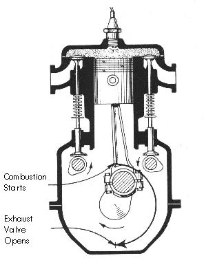
During the power or expansion stroke, the hot gases obtained by combustion exert tremendous pressure on the piston to force it to move downward, but near the end of the stroke this pressure is greatly reduced because of the expansion of the gases. At this stage, the exhaust valve opens as the crankshaft continues to revolve and the piston is again moved upward in the cylinder by the connecting rod. The burning gases remaining in the cylinder are forced out through the exhaust valve, hence this stroke is usually called the exhaust stroke, although it may be called the scavenging stroke for purposes of instruction. This is event No. 5. One engine cycle has been completed. To summarize the events, it is found that the charge of fuel and air was admitted into the cylinder during the intake stroke (event No. 1); the piston compressed the fuel-air mixture during the compression stroke (event No. 2); the electric spark ignited the compressed fuel-air mixture as the piston approached the top of its stroke within the cylinder (event No. 3); the fuel-air mixture burned and the expanding gases drove the piston downward during the power stroke (event No. 4); the burned gasses were forced out of the cylinder during the exhaust stroke (event No. 5)." This five-event sequence of intake, compression, ignition, power, and exhaust, is a cycle which must take place in the order given if the engine is to operate at all, and it must be repeated over and over for the engine to continue operation. None of the five events can be omitted, and each event must take place in the proper sequence. For example, if the gasoline supply is shut off, there can be no power event, but the mixture of gasoline and air must be admitted to the cylinder during the intake stroke. Likewise, if the ignition switch is turned off, there can be no power event. Ignition must occur before the power stroke can take place. | |

 | |||
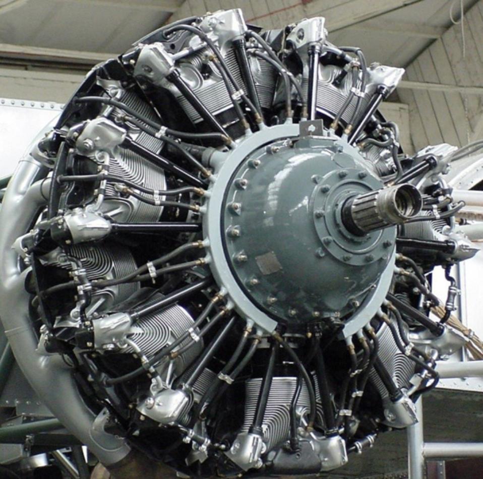
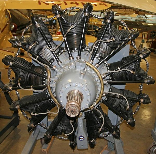
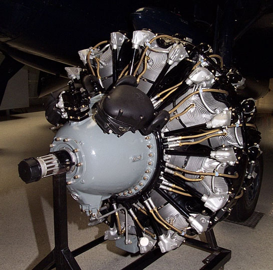
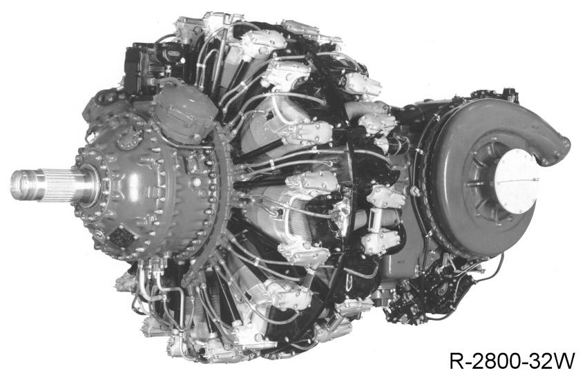
| Master-and-articulating-rod Assembly | |||
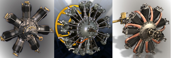
| The master-and-articulating-rod assembly is used on X-type engines, radial-type engines, and on some V-type engines. The master rod is similar to any other connecting rod except that it is constructed to provide for the attachment of the articulated rods on the big end. The articulated rods are fastened by knuckle pins to a flange around the master rod. Each articulated connecting rod has a bushing of nonferrous metal, usually bronze, pressed or shrunk into place to serve as a knuckle-pin bearing. The knuckle pins may be held tightly in the master-rod holes by press fit and lock plates or they may be of the full-floating type. | |||
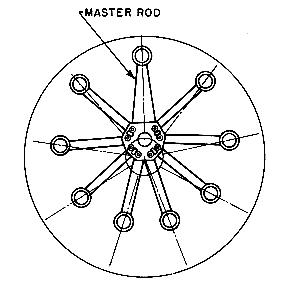 |
If the big end of the master rod is made of two pieces, the cap and the rod, then the crankshaft is made of one solid piece. On the other hand, if the rod is made of one piece, then the crankshaft may be of either two-piece or three-piece construction. Regardless of the type of construction, the usual bearing surfaces must be supplied. It should be understood that the type of connecting rod used in an engine depends largely on the cylinder arrangement. If the cylinders are arranged in a line parallel to the crankshaft, the connecting rod is similar to that used in most automobile engines. However, certain types of aircraft engines have a system of connecting rods connected to the same crankshaft bearing, called an articulating connecting-rod assembly. The main rod or master rod joins one of the pistons with the crankshaft, and the other rods, called articulating rods or link rods, connect the other pistons to this same master connecting rod. 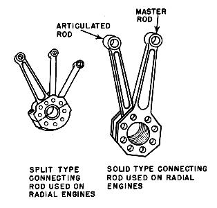 |


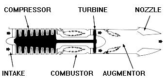 | ||
| A turbojet engine. | ||
| The turbojet is the basic engine of the jet age. Air is drawn into the engine through the front intake. The compressor squeezes the air to many times normal atmospheric pressure and forces it into the combustor. Here, fuel is sprayed into the compressed air, is ignited and burned continuously like a blowtorch. The burning gases expand rapidly rearward and pass through the turbine. The turbine extracts energy from the expanding gases to drive the compressor, which intakes more air. After leaving the turbine, the hot gases exit at the rear of the engine, giving the aircraft its forward push ... action, reaction ! For additional thrust or power, an afterburner or augmentor can be added. Additional fuel is introduced into the hot exhaust and burned with a resultant increase of up to 50 percent in engine thrust by way of even higher velocity and more push. | ||
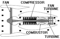 | |||
| A high bypass turbofan engine. | |||
| A turbofan engine is basically a turbojet to which a fan has been added. Large fans can be placed at either the front or rear of the engine to create high bypass ratios for subsonic flight. In the case of a front fan, the fan is driven by a second turbine, located behind the primary turbine that drives the main compressor. The fan causes more air to flow around (bypass) the engine. This produces greater thrust and reduces specific fuel consumption. | |||
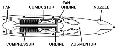 | |||
| A low bypass turbofan engine. | |||
| For supersonic flight, a low bypass fan is utilized, and an augmentor (afterburner) is added for additional thrust. | |||
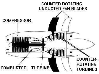 | ||
| A high bypass turbofan engine. | ||
| A logical approach to improving fuel consumption is even higher bypass technology. Mechanical arrangements can vary. During the 1980s, GE developed the Unducted Fan UDF® engine which eliminated the need for a gearbox to drive a large fan. The jet exhaust drives two counter-rotating turbines that are directly coupled to the fan blades. These large span fan blades, made of composite materials, have variable pitch to provide the proper blade angle of attack to meet varying aircraft speed and power requirements. Powerplants such as the UDF® engine are capable of reducing specific fuel consumption another 20-30 percent below current subsonic turbofans. | ||
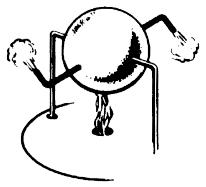 | |||
| Centuries ago in 100 A.D., Hero, a Greek philosopher and mathematician, demonstrated jet power in a machine called an "aeolipile." A heated, water filled steel ball with nozzles spun as steam escaped. | |||
| Over the course of the past last half century, jet-powered flight has vastly changed the way we all live. However, the basic principle of jet propulsion is neither new nor complicated. Centuries ago in 100 A.D., Hero, a Greek philosopher and mathematician, demonstrated jet power in a machine called an "aeolipile." A heated, water filled steel ball with nozzles spun as steam escaped. Why? The principle behind this phenomenon was not fully understood until 1690 A.D. when Sir Isaac Newton in England formulated the principle of Hero's jet propulsion "aeolipile" in scientific terms. His Third Law of Motion stated: "Every action produces a reaction ... equal in force and opposite in direction." The jet engine of today operates according to this same basic principle. Jet engines contain three common components: the compressor, the combustor, and the turbine. To this basic engine, other components may be added, including:
| |||